Caution!!- POTENTIALLY LETHAL VOLTAGES CAN EXIST IN THIS AMP, EVEN WHEN TURNED OFF OR UNPLUGGED. USE EXTREME CAUTION WHEN WORKING ON ANY HIGH VOLTAGE EQUIPMENT. THESE MODIFICATIONS SHOULD ONLY BE ATTEMPTED BY PERSONS FAMILIAR WITH THE NECESSARY SAFETY PRECAUTIONS! REMEMBER, YOU ARE RESPONSIBLE FOR YOUR OWN SAFETY AND THAT OF YOUR EQUIPMENT.
Easy Mods For The Citation II...
Triode Connecting Your Output Tubes - a very easy to perform modification, and very much worth a try, since it only
requires 4 resistors to accomplish! Here's how:
1. Remove the wires from pin 4 of the output tube sockets (all four tubes). Note: The amp may use pin 6 as a tie point.
In that case remove the wiring from pin 6 as well. Be sure to carefully insulate the bare wire ends, as they'll have 450+
volts on them when you turn on the amp!
2. Connect a 150-275 ohm 1/2 or 1 watt resistor from pin 4 to pin 3 on each of the four output tubes.
3. Reset bias and balance, and enjoy the music.
This change reduces the output power from 60 watts to about 35 watts, and reduces the amp's gain considerably (you'll
notice the volume control is set up higher to achieve the same loudness). It also reduces the loop negative feedback, which
accounts for some of the difference you hear.
I find this modification to be a "no-brainer". The amp acquires a sweetness and musicality that is very hard to beat. Plus
if you use the Genalex reissue KT-88 tubes, you'll find they work well triode connected in this amp. I have stock of these
again, see my tube page for details and pricing. In my opinion it is now the best tube for a Citation II in existence.
Reduce Bias Current While Retaining The Stock Bias Meter
The stock Citation II amp is set to run a bias current of 100 ma. through each of the output tubes if you set the bias
at the internal meter's "bias" mark. The "bias" mark corresponds to 1.5 volts dropped across the stock 15 ohm cathode
resistors. With today's higher line voltages, this means the tubes will be dissipating in excess of 45 watts at idle, which can
really shorten tube life. Especially 35 watt rated 6550 coke bottle Tung-Sols!
The solution is easy - replace the 15 ohm resistors from pin 8 to ground on each of the output tubes with a higher value. This
way the meter will still indicate the correct setting at the "bias" mark, but the current will be reduced to a more sane level.
My bias current recommendations are as follows:
For KT-88 EH or Genalex tubes: Install an 18 ohm 2 watt resistor for 80 to 85 ma. bias current.
For all other output tubes: Install a 20 ohm 2 watt resistor for about 75 ma.
Need resistors? See the H-K Citation Kits and Parts Page.
Be sure to reset the bias and AC balance when you finish, using the same procedure as for a stock amp.
Turn-On Surge Limiting For Your Amp
There is a lot of concern about the effect of the turn-on surge on these amps, especially the tubes. I have not seen any
problems in my own experience, but I do recognize that not everyone agrees with me on that point. I've looked carefully
at what could be done to reduce the surge, and while there are a variety of methods that can be used, I had some
"ground rules" that I applied:
1. The method had to be simple and easy to implement
2. There had to be room for the components even after installation of my power supply kits, and
3. The modification had to be installable without "Stu Hegeman" levels of expertise!
The best solution I found was use of specialized "inrush limiter" thermistors. These feature a long time constant, so this not
only reduces the strain on the power supply components, it allows a bit of a break for the tubes.
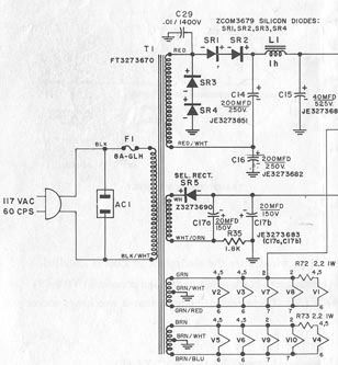
Citation II Power Supply - Stock Circuit Shown
The best place for installation of these limiters is in the 170 volt leads
(red and red/white wires on the Citation II power supply diagram at left)
from the power transformer, ahead of the diodes (you can install it instead
of the 5 ohm resistor present on many Cit V amps). Installed here, it allows
fast application of heater and bias voltages, but eases/slows the B+ a bit
without causing a problem after the amp is warm.
Extremely important! If you implement your own scheme with time delay
relays or ??, remember this: the bias voltage must come up before the B+!
Otherwise you'll have output tubes running away from lack of bias, and
damage to the tubes and amp are a likely result.
Need Parts? I've assembled an inexpensive "kit" of inrush limiters that work well
in the Citation II and V. You can install them yourself if you are handy with a
soldering iron in about an hour. See the H-K Citation Kits and Parts Page for details.
Here's the how-to, right from the original H-K manual:
In order to operate the Citation II as a 120 watt monophonic amplifier it is necessary to fulfill two requirements:
1. The speaker output terminals must be strapped together. Tie the two ground terminals in parallel and then tie either the
two 8 or 16 ohm terminals in parallel depending on the nominal impedance of your speaker. For example, if you are using
an 8 ohm speaker, tie the two 16 ohm terminals together and attach the speaker between either 16 ohm terminal and
ground. If you are using a 16 ohm speaker it is permissible to connect it as described for an 8 ohm speaker, as a
mismatch of as high as 50% will not affect the tone quality.
2. The amplifier input terminals must be tied together if no preamplifier is to be used and the signal is being fed directly
by a tuner. If a monophonic preamplifier is used it is also necessary to tie the inputs together. This can be accomplished in
any of several ways. One method would be to use two patch cords with RCA type phono plugs on one end. The other
end of these patch cords would be tied together in parallel and soldered to another RCA type phono plug. Connect the
two individual RCA plugs to the input receptacles of the amplifier and the other end (which is paralleled) to the output of
your tuner. A more satisfactory method is to purchase a LAB-TRONICS patching plug, Part #A-7 54 to parallel the
inputs of the amplifier. This device would eliminate the need of soldering and would insure perfect connections.
3. If a stereo preamplifier is used input strapping is not required. Merely connect the two outputs of your preamplifier to
the corresponding inputs of the Citation II and connect the speakers as previously discussed.
Note: The procedure is identical for the Citation V.
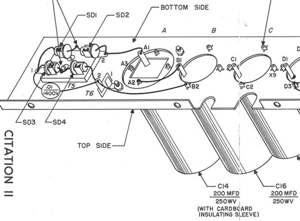
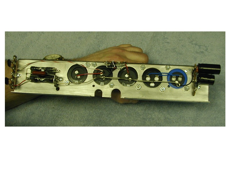
Another great way to improve performance of a Citation is to improve the grounding schemes in a couple areas.
Here's one - use T6 (on the pictorial above, next to the diodes) as your ground point. Use the mounting hole for
T6 and put a solder lug in its place, tighten it down so the lug bites into the bracket hard! This becomes your chassis
ground point. Run a 14 ga. bus bar to the ground tab on C16 (where the pictorial shows a piece of wire running),
and wire/solder all the electrolytic grounds to this bus directly.
Ground the bias circuitry to the same bus bar. BIG improvement here! And do be sure the mounting bracket is
grounded to the main chassis- I put a small tooth washer under the bracket to bite into the chassis when I reinstall
the bracket. I recommend you take the 4 screws out and lift the bracket out of the amp if/when you rebuild it.
General rule: All power supply and signal grounds go to the bus bar. AC grounds (heater winding CT, test
signal ground, and the meter ground) go to the chassis.
If you purchase any of my power supply upgrade kits these changes are even more effective! Redoing the
grounds are easy while you've got the bracket out on the bench, and the Level II kit takes you through the
G terminal situation (along with other key improvements).
More to come...
Check back soon!
To Home Page To Tubes Page To H-K Citation Kits and Parts Page To Citation II adjustment page
To Citation V adjustment page To Citation Resources Page (under construction)